
An engine misfire can quickly turn a routine drive into a stressful situation. While many owners rely on generic guides or forums, factory manuals provide the manufacturer-designed diagnostic steps. Neglecting these official resources is a common pitfall in misfire repairs.
Efficiently repair misfires by following the OEM service manual’s diagnostic tree in order. This approach prevents guesswork and unnecessary parts replacement. Factory manuals are superior because they offer vehicle-specific DTC definitions, exact pin-out voltages, and specialized flowcharts.
This guide explores how to interpret factory manuals for misfire faults, identifies key sections, and explains why these manufacturer-specific tests outperform aftermarket guides.
Using Factory Manuals for Engine Misfire Repair: What the Diagnostic Tree Really Tells You
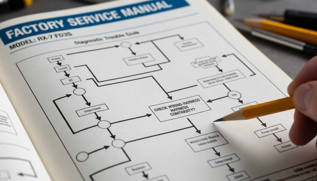
Factory service manuals are not just parts lists. They are structured, model-specific diagnostic systems built by the same engineers who designed the engine. Every misfire code, wiring diagram, and fuel trim specification in them is verified against real production data. Understanding how to navigate these manuals turns a frustrating repair into a logical, step-by-step process.
What Exactly Is an Engine Misfire, and Why It Matters
Before opening any manual, you need a clear picture of what a misfire actually is. A misfire occurs when combustion in one or more cylinders fails to complete normally. This can happen from a fuel, spark, or compression problem.
Factory manuals define misfires using specific OBD-II codes: P0300 for random misfires, and P0301 through P0312 for cylinder-specific events. These codes serve as the entry point for every factory repair tree.
Common symptoms of a misfire include a rough idle, engine shaking, loss of power, and increased fuel consumption. Catching these early and cross-referencing them with the factory manual saves both time and money.
| OBD-II Code | Misfire Type | Primary Suspect |
|---|---|---|
| P0300 | Random/Multiple Cylinders | Fuel delivery, ignition system |
| P0301 | Cylinder 1 Specific | Spark plug, coil, injector |
| P0302 | Cylinder 2 Specific | Spark plug, coil, injector |
| P0304 | Cylinder 4 Specific | Injector, valve, compression |
| P0316 | Misfire at Startup | Cold start enrichment, fuel pressure |
Finding the Misfire Section in Your Factory Manual Fast

Most technicians lose time searching for the wrong volume. Factory manuals are typically split across multiple volumes: Engine Mechanical, Engine Control, and Electrical Wiring. The misfire repair content is located within the Engine Control volume.
Once inside Engine Control, look for the section labeled DTC Diagnosis or Malfunction Indicator Lamp Diagnostics. Navigate to P0300 or the specific code pulled from your scanner. Each code has its own diagnostic flowchart.
If you are using a digital factory manual, use the search function with the exact DTC code. This bypasses the index entirely and takes you directly to the relevant engine repair procedure.
Reading the Diagnostic Flowchart Step by Step
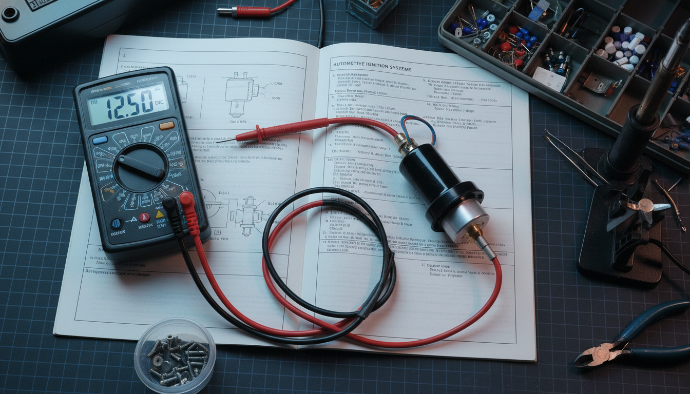
The diagnostic flowchart inside a factory manual is not decorative. It is a sequential test procedure where each step confirms or eliminates one cause before moving to the next. Skipping steps is how unnecessary parts get ordered.
Each node in the flowchart includes a specific measurement, a pass/fail value, and a branch for each outcome. This structure is what separates OEM documentation from any aftermarket repair guide.
Here is the standard sequence most factory manuals follow for a misfire repair diagnosis:
- Step 1: Confirm the DTC is active and record freeze frame data from the scan tool.
- Step 2: Perform a visual inspection of ignition wires, coil connectors, and vacuum lines.
- Step 3: Check spark plugs for wear, fouling, or incorrect gap per OEM specification.
- Step 4: Test coil-on-plug resistance using the values listed in the factory wiring diagram.
- Step 5: Verify injector operation with a noid light or oscilloscope against the factory manual waveform pattern.
- Step 6: Run a compression test and compare to the OEM specification table in the Engine Mechanical section.
- Step 7: Perform a fuel pressure test and confirm it meets the spec listed under fuel system diagnostics.
This process eliminates surface-level guessing. Every test result points to the next logical action, which is exactly how factory-trained technicians approach any engine misfire repair.
Interpreting Wiring Diagrams for Ignition and Fuel Circuits
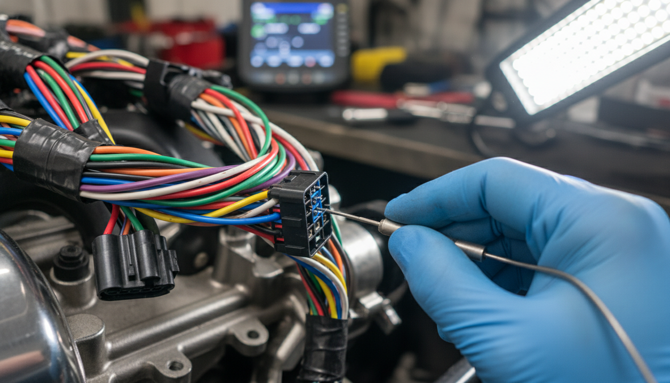
Wiring diagrams in a factory manual are the most underused diagnostic resource for misfire repair. They show every connector, pin number, wire color, and ground path for the ignition and fuel injection systems.
For a P0301 misfire, the wiring diagram shows exactly which ECU connector pin powers the cylinder 1 coil. You can backprobe that specific pin and confirm signal integrity without disassembling anything else.
Ground circuit faults are a leading cause of intermittent misfires and are almost impossible to find without the wiring diagram. The factory manual identifies every chassis ground point related to the ignition system by location and connector ID.
Misfire Repair Mistakes That Factory Manuals Prevent
The most expensive misfire repairs are those in which parts are changed before a proper diagnosis is complete. A replaced coil pack on a P0301 means nothing if the real fault is a corroded injector connector.
Factory manuals prevent this by requiring confirmation of measurements before any part replacement. If the coil resistance test passes, the flowchart does not send you to replace the coil. It sends you to the next test.
Some of the most common errors that factory manual procedures are specifically designed to eliminate include:
- Replacing spark plugs without checking ignition timing advance data from the scan tool.
- Swapping injectors without performing a cylinder contribution test first.
- Ignoring freeze frame data that shows the misfire only occurs under load at specific RPM ranges.
- Skipping compression testing when the factory manual flowchart routes you there as step three.
- Using non-OEM part specifications for spark plug gap or coil resistance ranges.
| Approach | Accuracy | Average Parts Cost | Time to Fix |
|---|---|---|---|
| Factory Manual Diagnosis | High | Low (targeted) | 1 to 3 hours |
| Generic Aftermarket Guide | Medium | Medium | 3 to 6 hours |
| Parts Swapping Without Diagnosis | Low | High (wasted parts) | 6 to 12 hours |
Using Factory Specs to Confirm a Complete Repair

Once the root cause is identified and the faulty component is replaced, the factory manual provides verification steps to confirm that the engine misfire is fully resolved. Clearing the code and road testing are not enough.
The manual will direct you to run a specific drive cycle that triggers the OBD-II monitor for misfires. Until the monitor runs and passes, the repair is not confirmed. This step is documented under the Readiness Monitor or Drive Cycle section.
Post-repair checks include verifying that fuel trim values are within spec using live-scan data, confirming that misfire counters are at zero across all cylinders, and checking that no new DTCs have appeared after the repair. The factory manual lists acceptable ranges for all of these parameters.
Conclusion
Using factory manuals for engine misfire repair is not a preference. It is the most reliable way to accurately diagnose, replace only what is actually broken, and confirm that the fix is complete.
Generic guides and forum advice get close. The OEM factory manual gets it right. Every wiring diagram, flowchart, and specification inside it exists because the manufacturer tested that exact procedure on that exact engine.
The next time a misfire code appears on your scanner, open the factory manual before touching any parts. That one habit will save hours of labor and hundreds of unnecessary component costs.