
Trying to read connector views in factory manuals without knowing the rules is a fast track to wrong diagnoses and damaged terminals. Miss one pin orientation detail in a factory service manual, and your entire electrical trace falls apart before you even touch the vehicle.
Manuals depict connectors from the terminal face, with numbering starting at a specific reference corner. Correct reading requires matching the physical connector to the mating face diagram. Technicians must follow a sequential numbering scheme, verify wire colors, and distinguish between the harness and component sides.
This guide covers how to decode connector views, understand cavity numbering, match wire color codes, and use the factory manual legend to trace faults with confidence.
How to Read Connector Views in Factory Manuals: The Skill That Changes Everything
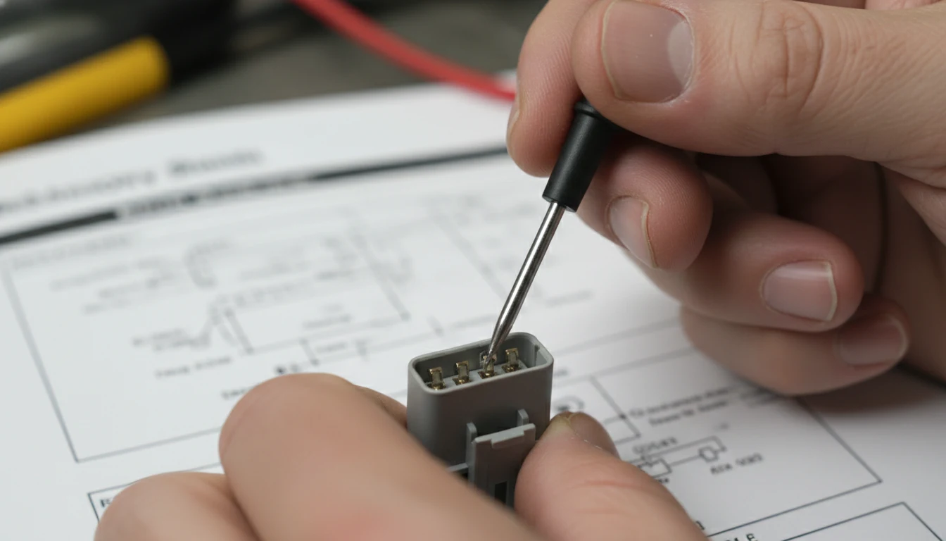
Most repair mistakes trace back to misread connector diagrams, not bad parts. Factory manuals pack a lot into a small sketch, and knowing exactly what each element means separates a confident diagnosis from a costly guess.
This section breaks down every layer of a connector view inside a factory manual, from orientation to terminal numbering, color codes to cavity status. Follow each step in order, and nothing will catch you off guard at the vehicle.
Step 1: Understand What a Connector View Actually Shows
Before touching a diagram, you need to know from what perspective it is drawn. This is where most readers go wrong at first glance.
Every connector view in a factory manual shows the connector’s terminal face in its disconnected state. That means you are looking at the side where the pins or sockets are exposed, not the wire entry side. This is sometimes called the mating face view or front face view.
- Male connectors show exposed pins pointing toward you
- Female connectors show open sockets or cavities facing you
- The factory manual will often label which side is shown, so check the caption or legend first
This single detail matters because if you flip the perspective and read the diagram from the wire side, every pin number you identify will be a mirror image of the real layout. That leads directly to probing the wrong terminal.
| View Type | What You See | Common Label in Manual |
|---|---|---|
| Terminal Face / Mating Face | Pins or sockets exposed | ”Connector End View” |
| Wire Entry Side | Wire exits, seal, or backshell | ”Harness Side View” |
| Component Side | Connector mounted to module | ”Component View” |
Factory manuals default to the terminal-face view unless otherwise noted.
Step 2: Find and Use the Connector Numbering System
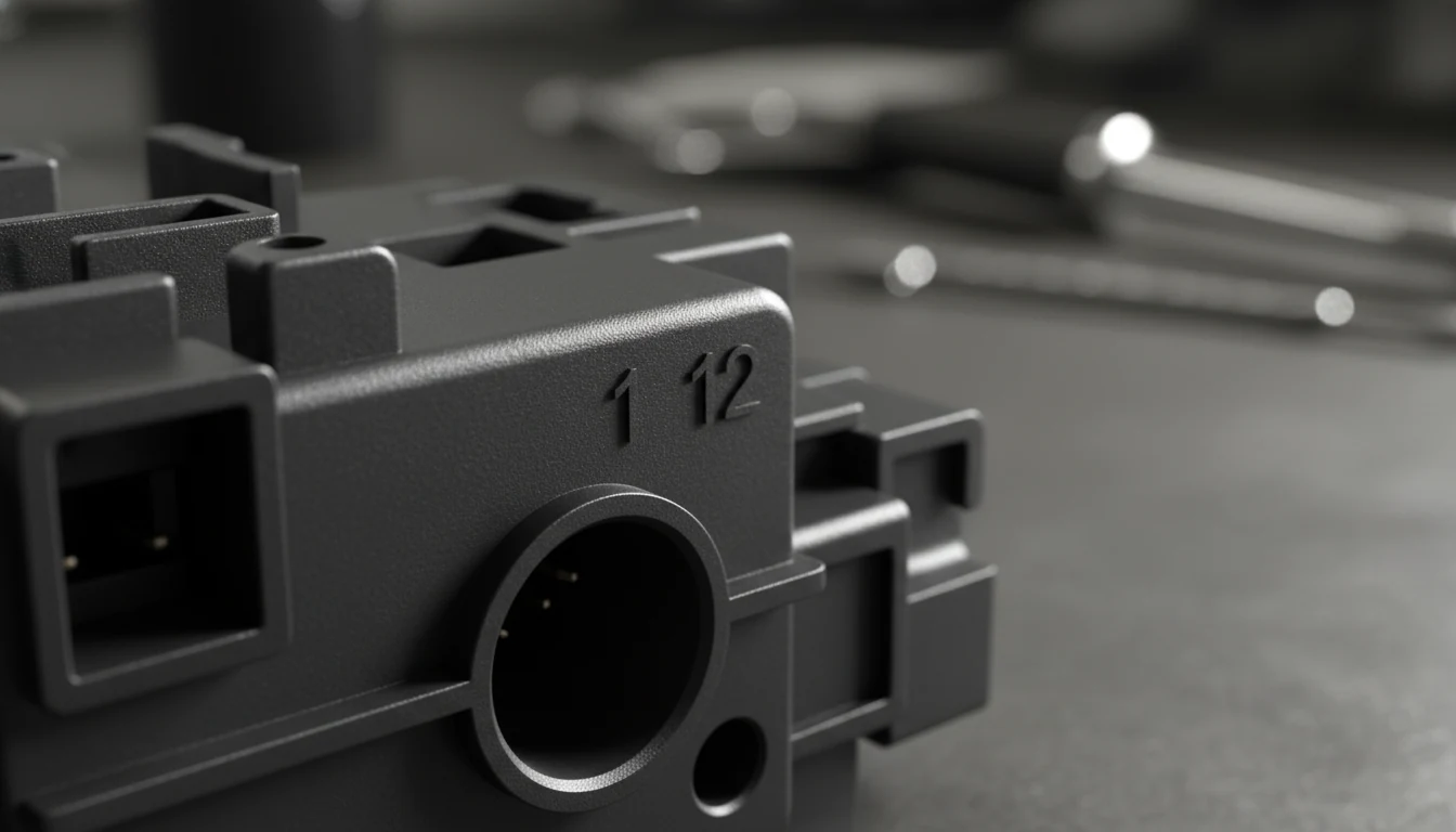
Every connector in a factory manual gets a unique identifier, and that number ties directly to the harness layout section of the same manual.
The connector number usually appears as a letter followed by a number. For example, a label like C34 indicates the 34th connector in the harness.
Some manufacturers use the first letter to indicate location: F for the front, E for the engine bay, and I for the interior.
Once you learn the system for your specific make, finding any connector in the vehicle becomes fast and predictable.
- Look for the connector reference table near the front of the electrical section in the factory manual
- Match the label on the diagram to the same label in the component locator
- Cross-check the pin count shown in the diagram against the physical connector before probing
Pin numbering in most factory manuals runs left to right, top to bottom, starting from pin 1 at a marked corner. GM manuals typically mold the number 1 and the last pin number directly into the plastic housing.
Step 3: Read Cavity Numbers and Identify Empty Terminals
Not every cavity in a connector carries a wire. Understanding how factory manuals show unused positions prevents miscount errors and stops you from probing the wrong terminal.
A blank or an asterisk symbol in a cavity usually indicates that the position is intentionally left empty for that vehicle configuration. Some factory manuals label these as “Not Used” with a dash or a small dot.
Never assume an empty-looking cavity is a fault. Always cross-check against the connector end-view table, which lists each cavity by number, along with its wire color and circuit function.
- Dashed outline around a connector sketch often indicates an optional or variant connector
- Solid outline means the connector is present on all builds of that model
- An X at the end of a connector number in some manuals indicates a sub-harness or pass-through junction point
This level of detail matters when you pull up a factory manual PDF and the connector view shows 10 cavities, but the physical plug only has 8 wires populated. That is normal, not an error.
Step 4: Decode Wire Color Codes in Connector Diagrams
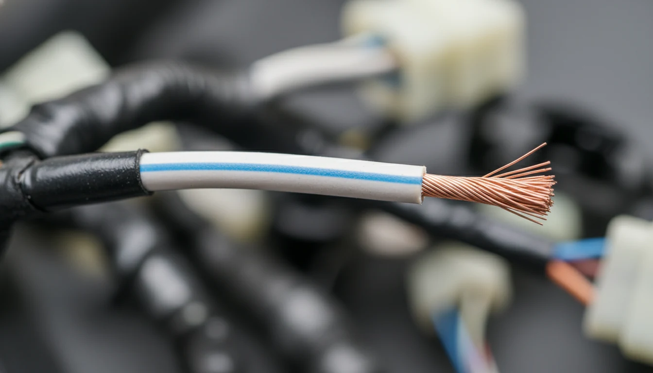
Factory manuals use a standardized color code system that is consistent across most makes once you understand the abbreviation format.
A two-part color code like B/W means the base wire color is black with a white stripe. The first letter is always the primary color, and the second is the tracer or stripe.
Some manuals drop the slash and write it as BW or use full words in a legend. Always check the wire color abbreviation table in the front of the electrical section before starting any trace.
| Abbreviation | Color |
|---|---|
| B | Black |
| W | White |
| R | Red |
| G | Green |
| L or Bl | Blue |
| Y | Yellow |
| Br | Brown |
| Gr | Gray |
| O | Orange |
| P | Pink |
Wire gauge is shown as a number alongside the wire line in the diagram, often in millimeters squared, such as 0.5 or 0.8. Thicker wires carry higher current, so this detail matters when testing voltage drop or replacing a damaged segment of wire.
Step 5: Cross-Reference the Connector View with the Circuit Diagram
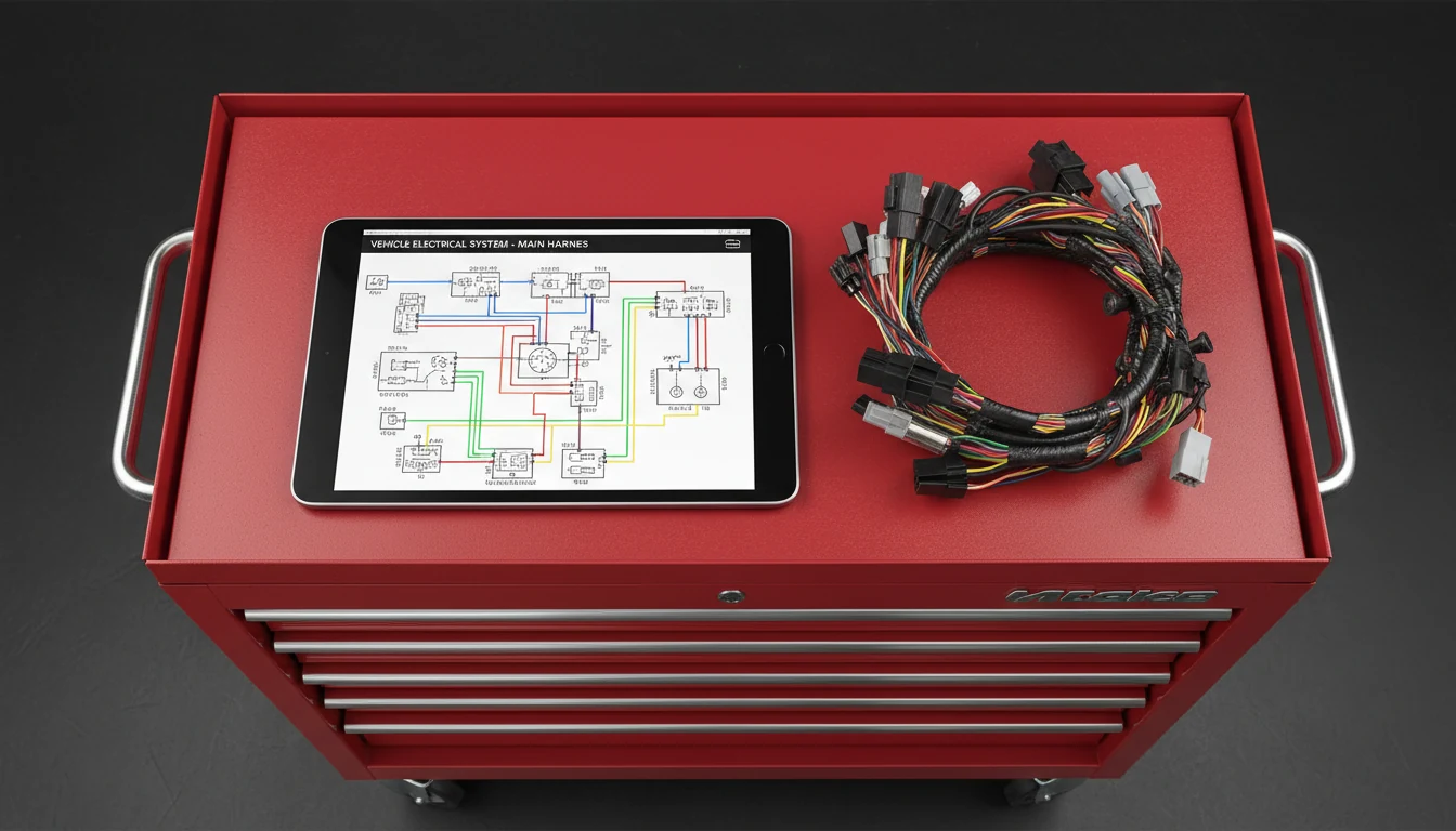
A connector view alone does not tell you what the circuit does. You always need both the connector end view and the main circuit schematic open simultaneously.
Start with the circuit diagram to understand how current flows from the power source to ground. Then use the connector view to confirm which physical pin in the actual harness corresponds to each circuit line on the schematic.
The factory manual ties these together through the connector reference number; the same label appears on the circuit diagram and in the connector end-view table.
- Trace from the battery positive downward through fuses, relays, and switches to the component
- When you reach a connector symbol on the diagram, switch to the connector end view to find the exact cavity
- Note the wire color, cavity number, and circuit designation before probing
- Use a high-impedance meter to avoid damaging sensitive control module circuits
For shops using digital factory manuals through platforms such as Mitchell 1 ProDemand or AllData, the connector view is usually just one click away from the main schematic. This speeds up the process significantly compared to flipping through printed pages.
Step 6: Avoid the Most Common Connector View Mistakes
Even experienced technicians get tripped up by a few specific errors when reading connector views in factory manuals. Knowing them in advance saves real diagnostic time.
The biggest mistake is assuming the diagram orientation matches how the connector sits in the vehicle. It rarely does.
The diagram always shows the terminal face, but in the car, it might point downward, sideways, or toward the firewall. Always orient yourself physically before numbering cavities on the actual plug.
- Never skip checking the factory manual PDF checklist before starting repairs to confirm you have the correct manual version for your exact build date
- Avoid common mistakes when using factory repair manuals, such as using a manual from the wrong model year, which changes cavity numbering entirely
- DIY mechanics should review why factory service manuals are essential for DIY work before attempting electrical diagnosis for the first time
A secondary mistake involves backed-out terminals. A terminal that has slipped back into the cavity appears electrically fine on the schematic but causes an intermittent open circuit at the connector.
The factory manual shows what a fully seated terminal looks like versus a displaced one, and that reference image is worth reading before probing any suspect connector.
Step 7: Use Ground Point and Splice Information Correctly
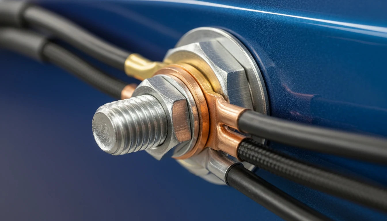
Connector views do not exist in isolation. Every circuit traces back to a ground point, and the factory manual shows exactly where each ground connects to the chassis.
Ground points are labeled separately from connectors, usually with a G prefix and a number. Each ground location corresponds to a physical bolt or stud on the body or frame. The factory manual includes a ground distribution diagram that shows which circuits share each ground. A single corroded ground bolt can disrupt multiple systems at once, and knowing this from the manual saves hours of misdiagnosis.
- Splice points in the harness are shown with a small dot or junction symbol on the schematic
- The factory manual assigns each splice a unique reference number so you can find it in the vehicle
- When tracing an intermittent fault, always check ground resistance at the listed ground point before condemning a component
For fluid system repair references alongside electrical work, checking how to find fluid capacity in factory manuals keeps all your factory data in one organized process.
Conclusion
Reading connector views in factory manuals is a skill built on a few firm rules: always view from the terminal face, use the connector reference number to cross-locate in the harness layout, confirm cavity status before probing, and always match wire color codes to the manual’s legend.
These steps are not complicated, but skipping any one of them can send a diagnosis in the wrong direction fast. The factory manual provides everything you need. The job is simply learning how to pull the right detail from the right page at the right moment.
Frequently Asked Questions
What does “connector end view” mean in a factory service manual?
A connector end view is the diagram perspective that shows the terminal face of a disconnected connector. It displays every cavity numbered from pin 1, along with the wire color and circuit function for each position.
This view is drawn as if you are looking directly at the open end of the connector, where the pins or sockets are exposed. The factory manual uses this view to let technicians identify exact terminal locations before probing or testing.
Always confirm that you are reading the terminal face side, not the harness entry side, because the two perspectives are mirror images.
Why do connector pin numbers look different in my vehicle versus the factory manual diagram?
This usually happens because you are reading the connector from the wire side rather than the terminal face. The factory manual always shows the mating-face view, so if you flip the physical connector around to view the wire entry, the numbering reverses.
Another cause is using a factory manual from the wrong build year. Some manufacturers updated connector layouts mid-production cycle without changing the model year designation, so always verify that your manual matches the actual build date on the doorjamb or in the VIN decoder.
How do I find which connector in the factory manual matches the one in my car?
Start with the connector reference table inside the electrical section of your factory manual. Each connector has a unique alphanumeric label that also appears on the harness layout diagram. The first letter usually indicates the vehicle zone, such as E for engine or I for interior.
Once you match the label, the factory manual’s component locator section shows a photo or drawing of the physical location on the vehicle.
Cross-checking the pin count and wire colors between the diagram and the actual plug confirms you have the right connector.
What does a dashed outline around a connector sketch mean in a factory manual?
A dashed outline in a factory manual connector view typically indicates an optional connector that is not present on all builds of that vehicle. It may represent a connector used only on specific trim levels, engine options, or regional configurations.
Some factory manuals also use dashed lines to distinguish the male side of a connector pair from the female side.
Always check the diagram legend at the front of the electrical section to confirm how your specific factory manual uses dashed versus solid outlines, since conventions vary slightly between manufacturers.
Can I use a factory manual from one model year to read connector views on a slightly different year?
In most cases, no. Connector cavity numbering, wire colors, and harness layouts can change from one model year to another, even when the vehicle looks nearly identical. Using the wrong factory manual year is one of the most common sources of diagnostic errors for both professionals and DIY mechanics.
Manufacturers sometimes update a harness mid-cycle without announcing it publicly, and the only reliable way to catch those changes is to match your factory manual exactly to the build date on the vehicle identification label.
When in doubt, pull the correct year-specific data before starting any electrical diagnosis.