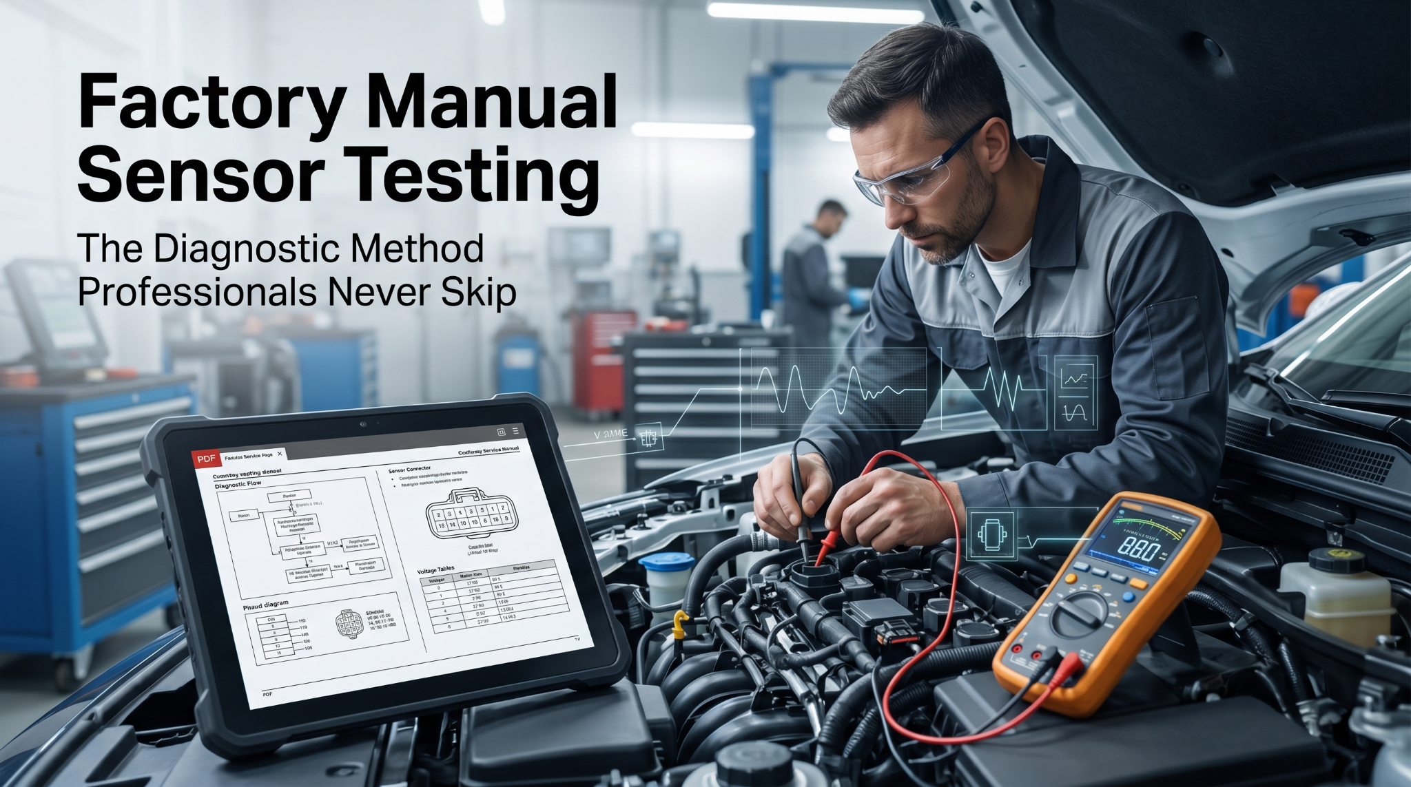
When factory manuals, sensor testing procedures, and proper diagnostics are skipped, technicians routinely replace working parts and waste serious money. Ignoring what these manuals explain puts every repair job at real risk of failure.
Factory service manuals provide essential voltage, resistance, and test sequences based on real operating conditions. Professionals use them with a digital multimeter (DVOM) to validate power, ground, and signal output against manufacturer standards.
This article walks through exactly how to read and apply sensor testing procedures from factory documentation, covering reference values, multimeter use, fault interpretation, and common errors that cost time and parts.
How Factory Manuals Explain Sensor Testing: What Most Guides Hide
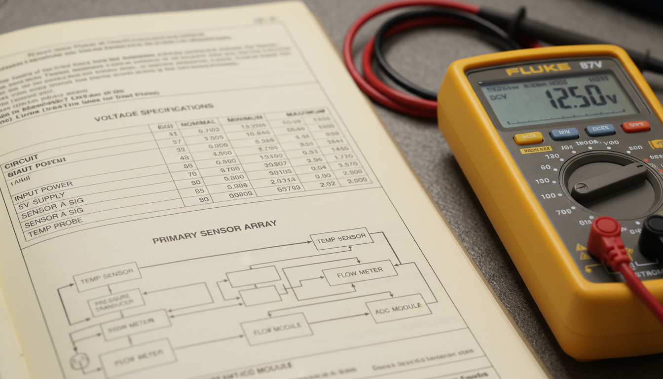
Most online tutorials skip the part that actually matters. Factory manuals do not simply describe sensors. They define the exact conditions under which each sensor must be tested, and what each reading should mean.
This article covers how to extract that information correctly, apply it to real tests, and avoid costly assumptions that lead to wrong part replacements.
Factory Manuals Don’t Guess: They Give Exact Specs
Before touching a sensor, knowing where to find the manufacturer’s own data is critical. Most DIY mechanics rely on general voltage ranges posted on forums, which is one of the biggest diagnostic mistakes.
Factory manuals publish sensor-specific data that generic guides simply do not carry:
-
Operating voltage range (e.g., 0.5V to 4.5V for many MAP sensors)
-
Expected resistance at specific temperatures for thermistor-based sensors
-
Signal frequency or duty cycle for digital output sensors
-
Idle vs. load values to compare against live data streams
This level of detail is not available in aftermarket guides. As covered in Why DIY Mechanics Need Factory Service Manuals, the gap between factory data and generic repair sources is significant. A sensor reading 2.1V might be fine on one engine and faulty on another. Only the factory manual tells you which is which.
Always locate the sensor specification table before running any test. This prevents guesswork from the start.
How Factory Manuals Structure the Sensor Test Procedure
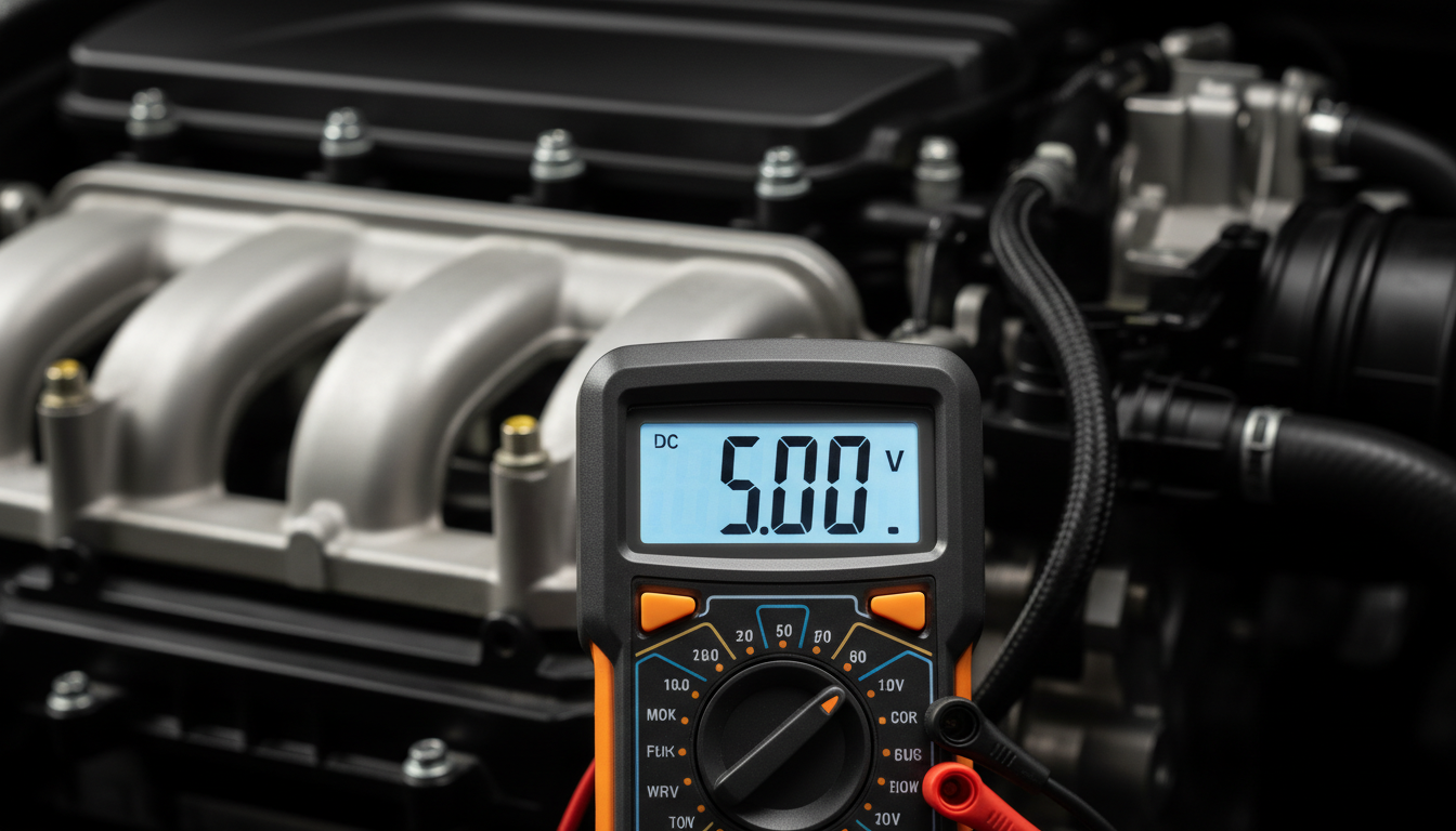
Every sensor-testing section in a factory manual follows a predictable format once you know what to look for. Understanding that structure saves serious time on every job.
Most factory manuals break sensor testing into these ordered steps:
-
Precondition the vehicle (engine temp, ignition state, accessories on or off)
-
Back-probe the connector without breaking the circuit
-
Measure reference voltage at the sensor supply wire
-
Measure signal output and compare to the spec table
-
Check ground integrity with a voltage drop test
Each step carries a pass/fail condition. If the reference voltage is missing, the sensor itself is not at fault. This is how factory manuals explain where the problem actually lives.
Technicians who skip step one often misread results. A cold-engine sensor will never match the warm-engine specs listed in the manual. That mismatch causes unnecessary replacements.
Follow each precondition listed in the manual exactly. Temperature and load state directly affect sensor output values.
Reading the Wiring Diagram Before You Test Anything

Sensor testing without understanding the circuit first leads to wasted time and damaged connectors. Factory manuals always pair sensor test procedures with a dedicated wiring section.
The wiring diagram shows:
-
Pin assignment for each wire at the sensor connector
-
Wire color codes for supply, signal, and ground lines
-
Splice locations that could introduce voltage drops
-
Module connections that share the same circuit path
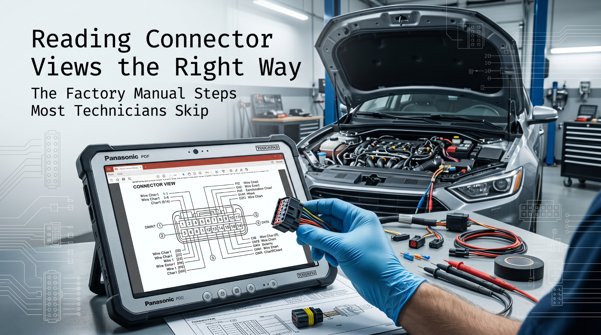
This matters because a failed sensor reading often stems from a wiring fault, not the sensor itself. Before back-probing, confirm which pin is the signal wire using the connector view diagram.
For a detailed look at reading those diagrams correctly, How to Read Connector Views in Factory Manuals covers the full process step by step.
Identify all three wires (power, signal, ground) from the wiring diagram before touching the connector.
How to Interpret Factory Manual Sensor Fault Criteria
Knowing what the numbers mean is just as important as collecting them. Factory manuals define fault thresholds that separate a borderline sensor from a confirmed failure.
Key fault indicators in factory manual sensor sections include:
-
Out-of-range voltage that persists across multiple key cycles
-
Slow response time compared to the manual’s expected reaction speed
-
Signal dropouts or flatline readings under dynamic conditions
-
Correlation failures where the sensor value does not match other system data
Some manuals include a sensor substitution test, in which a known-good sensor temporarily replaces the suspect unit. This step is listed as a confirmation tool, not a first response. Using substitution before completing circuit tests wastes parts and time.
A confirmed fault requires both an out-of-spec reading and a clean circuit test. That combination is what the factory manual demands before any part is ordered.
Factory Manual Sensor Test: Pass and Fail Reference
| Test Type | What It Checks | Pass Condition | Fail Indicator |
|---|---|---|---|
| Reference Voltage | Power supply to sensor | 4.9V to 5.1V (typical) | Below 4.5V or absent |
| Signal Output | Sensor response value | Within spec table range | Fixed, flatline, or out of range |
| Ground Voltage Drop | Circuit integrity | Below 0.1V | Above 0.2V |
| Sensor Substitution | Component confirmation | Value returns to spec | No change after swap |
| Response Time | Dynamic signal speed | Matches manual’s rate spec | Slow or no reaction |
Common Errors When Applying Manual Sensor Tests
Even with the factory manual open, certain mistakes keep appearing during sensor testing. These errors usually come from rushing the process or skipping the listed preconditions.
The most frequent issues include:
-
Testing without back-probing: Unplugging a sensor changes the circuit and produces false readings
-
Ignoring key-on vs. engine-running state: Some sensors only output values when the engine is running
-
Using the wrong meter setting: AC vs. DC voltage errors are common with O2 sensor testing
-
Missing the ground test: A weak ground makes a perfectly good sensor appear faulty
-
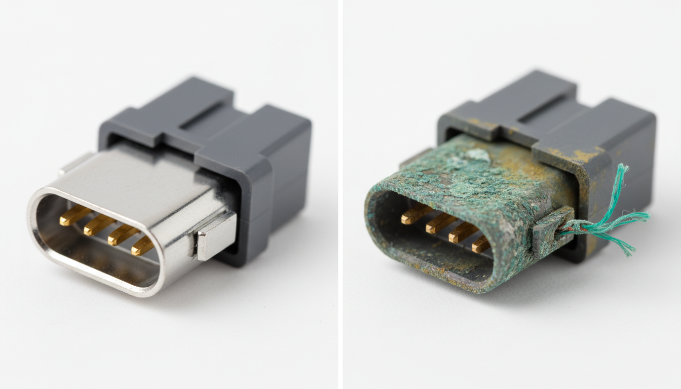
Skipping the connector inspection: Corroded terminals alter resistance and signal values
Before starting any sensor test, reviewing the Factory Manual PDF Checklist Before Starting Repairs helps confirm every precondition is met before touching a meter.
For a broader look at diagnostic errors that affect manual-based repairs, Common Mistakes When Using Factory Repair Manuals breaks down the most damaging habits technicians develop over time.
Sensor testing yields accurate results only when the circuit, conditions, and procedure match what the manual specifies.
Final Takeaway
Factory manuals are the only source that explains sensor testing with the precision that real diagnostics demand. They define specs, structure procedures, and set fault criteria that no aftermarket guide can replicate.
Following them step by step, from preconditions to circuit tests to fault confirmation, is the difference between an accurate diagnosis and an expensive guess. Keep the manual open, follow the sequence, and trust the data it provides.