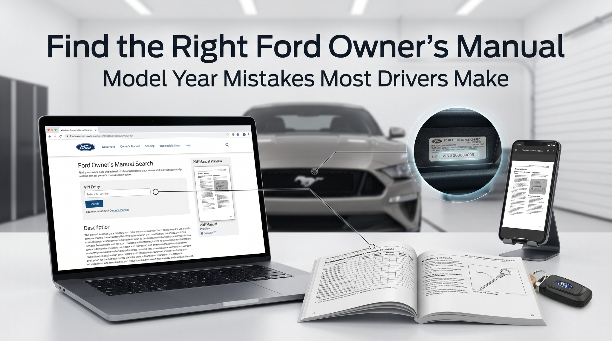
A no-start condition is one of the most frustrating problems a vehicle owner can face, and skipping the factory manual is the single biggest mistake made in early diagnosis. Without the right help from a manufacturer-approved manual, guesswork replaces real testing.
Follow the manufacturer’s diagnostic sequence to resolve issues quickly. Success relies on distinguishing between No-Crank and Crank-No-Start conditions using systematic factory processes.
This article covers the essential steps, common failure points, and how to read factory documentation like a seasoned technician.
Factory Manual Help for No-Start Diagnosis: What Most Guides Get Wrong
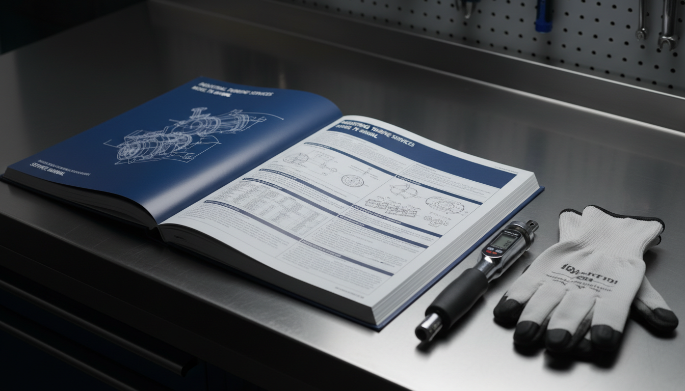
Most DIY troubleshooting advice treats a no-start as a simple three-step checklist. It rarely is. A proper factory manual provides vehicle-specific diagnosis flowcharts, wiring diagrams, and component specifications that generic guides simply cannot match. The help these documents provide is irreplaceable because manufacturers sequence their tests differently, and skipping even one step can yield a false result that costs time and money.
Step 1: Confirm Crank vs. No-Crank Before Anything Else
Before opening the factory manual to any specific section, you must establish which condition you are dealing with. This single observation drives the entire diagnosis path. Getting this wrong sends the entire repair in the wrong direction from the start.
- No crank, no sound: Points to battery, starter circuit, or inhibitor switch issues.
- Cranks but will not fire: Points to fuel, spark, or sensor signal failures.
- Single-click, then silence: Typically, a weak battery or a bad starter solenoid.
- Rapid clicking: Usually due to insufficient cranking voltage from a discharged battery.
Your factory manual will have a dedicated no-start diagnostic flowchart tied directly to these two scenarios. Find the correct one before touching any component. Jumping ahead without this confirmation is the most common mistake covered in common mistakes when using factory repair manuals.
Step 2: Pull Stored DTCs With an OBD2 Scanner Immediately
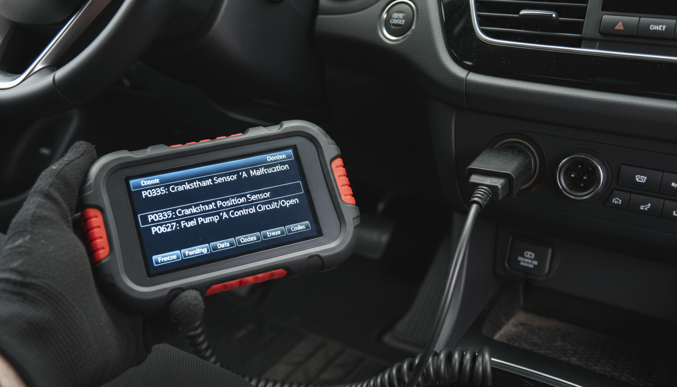
Many technicians wait until after physical inspection to scan for codes. The factory manual specifically instructs you to scan first because stored Diagnostic Trouble Codes directly reference the circuit or sensor that triggered a no-start event. Stored codes narrow the diagnostic field significantly before you touch a single component.
- P0335 / P0336: Crankshaft position sensor signal fault, common cause of crank-no-start.
- P0340 / P0341: Camshaft position sensor issue, disrupts injection and ignition sync.
- P0627 / P0628: Fuel pump control circuit faults that prevent fuel delivery.
- U-codes (network faults): ECM communication loss can block all starting functions.
Even if no codes appear, the factory manual tells you to record the live data stream during cranking. Watch for the engine RPM to drop to zero while cranking. A zero-RPM signal with confirmed cranking indicates a failed crankshaft position sensor.
| OBD2 Code | System Affected | No-Start Link |
|---|---|---|
| P0335 | Crankshaft sensor | No spark, no injection |
| P0087 | Fuel pressure low | Engine cranks, no fire |
| P0230 | Fuel pump circuit | No fuel prime pulse |
| P0601 | ECM internal fault | Complete no-start |
| P1632 | Battery voltage low | Starter won’t engage |
Step 3: Verify the Three Core Starting Requirements
Every engine needs exactly three things to start. Your factory manual breaks down diagnosis into these three branches and provides specific test values for each. Generic guides list these items, but never tell you where the pass/fail thresholds actually are.
Fuel Delivery:
- Check fuel pump prime pulse when ignition is first switched on (a brief hum from the tank).
- Use a mechanical fuel pressure gauge matched to the rail pressure specified in your factory manual.
- A 2024 four-cylinder gasoline engine typically requires 55-65 PSI at the rail during cranking.
- Low pressure indicates a failed pump, a clogged filter, or a faulty pressure regulator.
Ignition Spark:
- Remove one plug wire or coil-on-plug unit and use a spark tester, not bare-wire checks.
- Your manual specifies the minimum spark intensity required for reliable ignition.
- No spark with a confirmed crank RPM signal almost always traces back to the ignition coil driver circuit or the ECM output.
Compression Integrity:
- Rarely checked early enough in a no-start diagnosis.
- A broken timing belt or a jumped timing chain creates a crank-no-start with fuel and spark present.
- The factory manual contains TDC alignment marks specific to your engine; consult them before assuming a mechanical failure.
Step 4: Test the Crankshaft Position Sensor by the Numbers
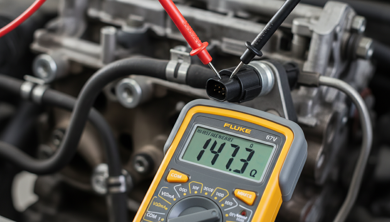
The crankshaft position sensor is responsible for more no-start conditions than any other single component on modern fuel-injected vehicles. Without a valid crank signal, the ECM will not fire injectors or trigger ignition. The factory manual gives you the exact resistance and voltage values. Do not substitute generic online specs.
- Locate the sensor using the factory manual wiring diagram, not a parts-store lookup.
- Disconnect the connector and set the multimeter to resistance mode.
- Compare the reading to the manual’s specification table. Most sensors fall between 200 and 1,000 ohms, depending on the manufacturer.
- A reading of zero (shorted) or infinity (open circuit) confirms sensor failure.
- Also, inspect the reluctor ring on the crankshaft for physical damage or missing teeth.
| Test Type | Tool Needed | Pass Condition |
|---|---|---|
| Resistance check | Multimeter | Within factory spec range |
| Voltage output | Oscilloscope / DVOM | Clean AC waveform during crank |
| Air gap | Feeler gauge | Per factory spec (typical: 0.020-0.050 in.) |
| Wiring harness | Visual + multimeter | No corrosion, shorts, or open circuits |
Step 5: Follow the Factory Diagnostic Form in Sequence

Professional service centers use a structured diagnostic form built directly into the factory manual. This form prevents technicians from performing tests out of sequence, which the manual explicitly warns can produce incorrect results. Skipping steps or changing the test order is not a shortcut. It is a diagnostic error.
- Begin with the battery and charging system test, as low voltage contaminates every downstream test.
- Proceed to the starter circuit test before touching fuel or ignition systems.
- Move to fuel system pressure and volume tests after confirming the starter circuit is intact.
- Test the ignition system only after fuel delivery is confirmed.
- Reserve ECM and network diagnosis for last, as they require all other systems to be tested clean first.
No-Start Diagnosis at a Glance
| Symptom | Most Likely Cause | Factory Manual Section |
|---|---|---|
| Silent with the key turn | Dead battery / bad starter relay | Electrical / Starting System |
| Rapid clicking | Low battery voltage | Battery / Charging System |
| Cranks, no fire, no codes | Bad crank sensor / no RPM signal | Engine Controls / Sensors |
| Cranks, no fire, fuel codes | Fuel pump or regulator failure | Fuel System |
| Cranks, no fire, ignition codes | Ignition coil or ICM failure | Ignition System |
| No crank after timing job | Timing marks incorrect | Engine Mechanical |
Conclusion
A no-start condition almost never has a single cause, and without factory manual support, the diagnosis process becomes an expensive trial-and-error process. The steps above follow the same logic built into every manufacturer’s diagnostic sequence: confirm crank vs. no-crank, scan for codes, verify the three core requirements, test the crankshaft position sensor against factory specs, and follow the diagnostic form in order. Skip any one of these steps, and you risk replacing parts that were never the problem.